- Joined
- Feb 14, 2011
- Messages
- 403
- Reaction score
- 3
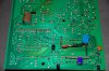
This evening I successfully implemented the RC filtering on the data lines with the values suggested (1K and 5.6pF).
The previous problem I had was just a dry joint. The tiny 1206 SMD caps have tinned ends which are really easy to overheat if you aren't very careful.
I'm listening to it now and wow it sounds good! That's a great little mod Martin, thanks for sharing.")
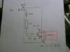
I also took the opportunity to rethink the power lines to the clock PSU and SAA7220 PSU. I've now tapped into the 230vac from the underside of the main PCB, after the ceramic disc cap the following inductor and also after the PCB mounted fuse so everything is fused from one main fuse now. Having everything arranged this way is much neater. I upped the fuse slightly from 160mA to 250mA to take into account the extra inrush current on switch on which it will have to deal with.
The previous problem I had was just a dry joint. The tiny 1206 SMD caps have tinned ends which are really easy to overheat if you aren't very careful.
I'm listening to it now and wow it sounds good! That's a great little mod Martin, thanks for sharing.
I also took the opportunity to rethink the power lines to the clock PSU and SAA7220 PSU. I've now tapped into the 230vac from the underside of the main PCB, after the ceramic disc cap the following inductor and also after the PCB mounted fuse so everything is fused from one main fuse now. Having everything arranged this way is much neater. I upped the fuse slightly from 160mA to 250mA to take into account the extra inrush current on switch on which it will have to deal with.